EZ-LITE modules work equally well in most scales, and are particularly suitable where space is at a premium. The voltage supplied to MOST modules must not exceed 16 VDC peak. (Full wave rectified AC is acceptable, as long as the peak voltage does not exceed 16 volts.)
For the EZ07, EZ08 and EZ09 modules, the PEAK voltage rating is 35 volts. The EZ54 rating is 24 volts RMS.
Many popular model railroad throttles are capable of supplying 28 to 30 volts PEAK output at full throttle. This will damage those EZ-LITE modules that are rated for 16 volts PEAK. Please remember that digital voltmeters and the voltmeters found on the throttles themselves read AVERAGE voltage, not PEAK voltage, and the PEAK voltage is always greater except for pure DC voltage. Typically the PEAK value is about 2.8 times greater than the AVERAGE reading at low throttle settings, dropping to about 1.4 times greater than the AVERAGE value at full throttle. If you are not sure about your throttle, please call for assistance.
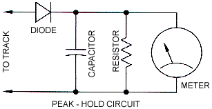
MAKING AN INEXPENSIVE PEAK-HOLD CIRCUIT
You can make a simple circuit which will allow your digital voltmeter to read PEAK voltage - all you need is an appropriate diode, resistor and capacitor. We recommend a 1N4001 diode (1 amp, 50 volts), but any rectifier diode rated the same or higher will work. The capacitor should be an electrolytic or tantalum capacitor rated for at least 100 µF and 50 volts. The resistor can be any wattage, and its value should be about 10K ohms. These are standard components at Radio Shack.
Hook the diode negative lead (marked by a line) to the capacitor positive lead. (For some capacitors, only the negative lead is marked with a "(-)" symbol -- obviously, the positive lead is the other lead.) Connect the resistor across the capacitor.
The diode will charge the capacitor to the peak track voltage, and it prevents the capacitor from discharging back into the track. The resistor will slowly bleed off the capacitor voltage over a period of about a second after power is removed.
Hook this assembly between your rails, with the diodes free lead (the anode) connected to the positive rail, and the capacitors negative lead connected to the negative rail. Connect your meter across the capacitor and measure the voltage. This will be the peak voltage.
If you now remove the peak-hold circuit and measure the voltage directly across the track, you can tell a few things about the voltage waveform present. For example,
If you find peak voltages over 16 volts, we can help you deal with the problem - please feel free to call.
RICHMOND CONTROLS (281)342-4895